
Arduino Space Invaders
Most of the microcontroller based hardware that I develop uses some form of AVR, so when I needed to evaluate some Arduino boards it was not much of a problem because as you most likely know, they too use AVR microcontrollers. At the time I decided that a simple game on an Arduino might be a fun way to test things. After completion I got the idea to publish it as a tutorial for beginners showing how to use Arduinos for games. Unfortunatly I never managed to finish the tutorial due to ‘paying’ projects taking priority.
Even though the tutorial was never finished, it along with the source code could still be of some help to anyone interested in game writing on a microcontroller. I have therefore decide to publish the section that was done. It covers mostly the hardware description along with the graphic layout and explanation.
Here goes….
What to do?
So you are sitting looking at your shiny new or perhaps not so new Arduino and thinking … what can I do with it. You have already said “Hello World; made LED’s flash and sent messages to your PC – so what’s next? Let’s write a game. At first you might think this will be a bit difficult if you are just starting out but with a little help it might be easier than what you think.
The Game
Space Invaders was one of the first video games written where the ‘machine’ fought back. So I have chosen this game as a good starting point to writing games on an Arduino.
What do you need?
You will need an Arduino. I have written and tested this game on an Arduino Duemilanove clone board. The display used is a small inexpensive Nokia 5110 LCD display.
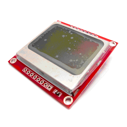
Of course if you are feeling brave you could salvage one from and old cell phone. This display expects to be connected to a 3.3v system. If your Arduino board does not have the option to run on 3.3v you will need some extra circuitry. To keep things simple I have used a 4X4 Keypad shield with display interface.
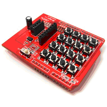
This shield allows you to use 5v or 3.3v. Apart from providing a simple interface for the LCD it also provides the buttons that you will need for the game. If you do not use this shield you will need to change the button inputs to suit whatever inputs you are using.
Note
If you choose to use 5 volts then on the keypad make sure jumpers are removed – jumpers bridge out limiting resistors on boards also set switch to 5 volt on keypad and Arduino
LCD
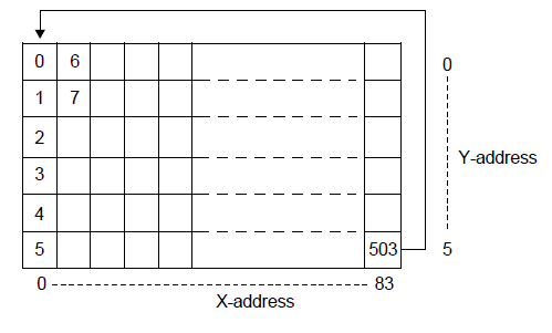
Ok its time to take a closer look at the display. The 5110 LCD is arranged as a matrix of 84 pixels across and 48 pixels down. Being a simple black and white display each pixel has only two states. It can be on / black or off / white. This allows us to control each pixel with just one bit. Unfortunately as I am sure you know by now, not everything is simple and neither is the layout of the bytes that make up the pixels of the LCD. The following image shows how the screen is laid out. At the bottom the X axis is marked showing the pixels across starting at 0 and going to 83.
The 0 to 5 shown on the Y axis represents the 6 bytes each containing 8 bits that make up the 48 pixels from top to bottom. Not shown in this diagram is the fact that the lowest valued bit column is toward the top of the LCD in each byte. So if we wanted to turn the the pixel on at the top left of the screen we would put a 1 which is binary 00000001 in the first byte and if we put 0x80 which in binary is 1000000 it would turn on the pixel in the 8th row from the top.
Don’t get too concerned about this, the library provided below will do all the heavy lifting for you.
Lets Start Coding
Before starting let me make some things clear. The object of this article is to demonstrate that writing a game for Arduino does not have to be too complicated. It is aimed at beginner level and up. I have therefore chosen to keep the code as basic and simple as possible and have avoided more advanced methods wherever possible. It is therefore not aimed to teach the best coding methods but rather aimed at keeping things simple enough to follow and understand.
The Enemy
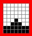
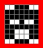
Now that we have a good idea of how the screen is laid out we can look at some of the items that will be displayed. Being an invaders game we need some invaders. Just as in the original game we have three different invaders. In order to give them some basic animation each invader has two different bitmaps. Let’s look at one of them and see how we get the image into our code.
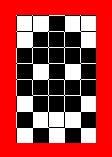
We can see that it is 8 pixels high and 5 pixels wide. To make it easy to use in our program we will convert it to hexadecimal. The bitmap has been laid out the same as the display. Each column is a single byte with the least significant bit toward the top. To convert it we do the following. Assign a value to each row starting at the top as follows.
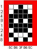
Start in the left most column. Start at the top and add the values in the first 4 rows in this column, where the pixels are on (black). The total is 12. We express that as a hexadecimal value ‘C’ . Now add the fields in the remaining 4 rows in this column, which are on. This gives 5. Remembering that the bits toward the bottom represent the most significant values. We combine them together to get the hexadecimal value of 5C. In the C programming language this is written as 0x5C.
We do the same for each column and will get the following values: 0x5C,0xB6,0x3F,0xB6,0x5C. We can now put these into an array. To help our image handling functions we will also put the number of columns making up our image (the width) into the array. This invader is 5 pixels wide.
Our array definition looks like this: unsigned char Invader[6] = {0x05,0x5C,0xB6,0x3F,0xB6,0x5C};
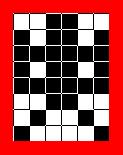
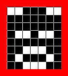
That was easy…. maybe too easy? Don’t forget that I said there were two images for each invader to give some animation. Say hello to his deformed twin:

Together we get:
The array for this one is: Invader[6] = {0x05, 0xDC,0x36,0x3F,0x36,0xDC };
To keep everything together and to make our program a little easier we will put both of them in one two dimension array.
unsigned char InvTop[2][6] PROGMEM =
{
{0x05,0x5C,0xB6,0x3F,0xB6,0x5C},//inv0
{0x05,0xDC,0x36,0x3F,0x36,0xDC} //inv1
};
Let examine this declaration. We have InvTop[2][6]. This simply says that this array contains two arrays each holding six bytes of data. PROGMEM ??? This is to tell the compiler to put this data into the Flash memory area of the processor instead of on the Ram area. We do this because the Ram area on this chip is only 1024 bytes whereas the Flash area is 8192 bytes. This does add another requirement when we want to use the data. We have to tell the compiler that it must look for the data in Flash and also provide it a method to read the data. We use the “pgm_read_byte” instructions.
Apart from the invaders we need a cannon, missiles, explosions, UFO and some shields. I have provided the shields but their use has not been coded. Here are the main actors
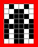
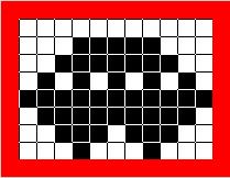
Each of them has been put into the code in the same way as detailed above
Start at the Top
We need to include a couple hardware libraries for the display and keypad
#include “IBridge_n5110_lcd.h”//libraries to control the LCD. You can get it here
#include “IBridge_Keypad.h”//keypad library. It is here
Once you have downloaded these files unzip them into the ‘libraries’ folder which you will find within the Arduino software path.
One last thing… download the main program file HERE 🙂