
Using mechanical quadrature encoders in your project
When I received the request to develop a down hill bike racing timer I thought that the Atmel Xmega would be the right tool for the job.
The system would need a 4 line LCD display with an easy to use menu system. The Xmega has a built-in Quadrature decoding feature, this influenced my decision to not only use buttons but also to include a quadrature encoder to allow for easy scrolling through menus and settings.
It sounded perfect. I decided to use the Alps EC12E24204A7 24 pulse encoder.
For those not familiar with a quadrature encoder lets take a quick look at what it looks like and what it does.
This decoder has 3 pins. One which is the common and 2 for the signals. It does not have an index pin. The index is so that you know when it has completed a revolution. We can do this in software.
From the outside it looks like a potentiometer:
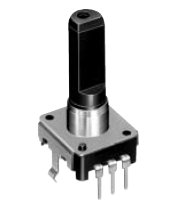
Internally it is just two switches that open and close in a specific relationship to each other.
The pins in my circuit are connected as shown below. Take note that this means that when the switch is closed the output will be 0 and will be a 1 when open
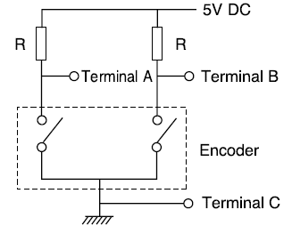
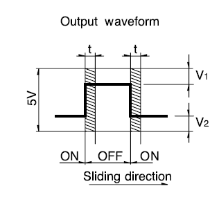
I used 4k7 resistors to pull the output up when the switch opens. This diagram shows the output of the encoder . The signals are 90 degrees apart.
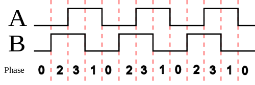
What is really important here is that this pattern will reverse if the knob is turned the opposite direction.
This allows us to see which direction the knob is being turned.
Turned clockwise we will get the signal shown above… 02310231 turned anticlockwise we will get 13201320 assuming that A is bit 0 of the port and B is bit 1.
If you connect A to bit 1 of the port and B to bit 0 the sequence will be the same but the direction of it will swap.
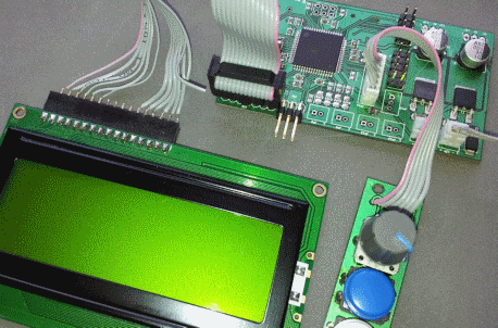
The build
I set about creating schematics and doing the PCB layout. I used Kicad for this part of the build.
I sent the Gerber files to the PCB manufacturer and within a week I had PCB’s that required assembly.
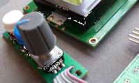
Within a few hours and I had assembled a working prototype.
After studying the Atmel application notes about the quadrature decoder I began writing the code. The built-in decoder makes use of the Xmega’s event system. The advantage of using events is that they only need configuration, at run time they have no impact on the code running.
I was soon to discover that there is also a disadvantage to using the event system, but more about that later.
I was so confident that this was the solution that I went ahead and wrote the code required for the LCD and Menu system. From a user perspective the operation would be simple.
Turn the knob of the encoder and the menu would scroll up or down. Press the enter button and the chosen menu item would be selected. Press cancel to abort or go back a level.
It does not work as advertised
I loaded the code into the Xmega and after fixing a couple of minor issues to get the LCD running I was ready to test the menu scrolling. I turned the knob and the menu jumped around erratically. Sometimes if you just touched the knob the menu would scroll and jump all over the place. This was not the result that I had expected.
The application notes made it all sound so simple. After double checking my code I started to question the encoder itself. I looked at the single page that has the data for most of the Alps encoders.
The first thing that I noticed was the position of the detent stability point. This is the position of the ‘click’ as you turn the knob. Looking at their diagram you can see right away that the slightest touch on the knob will cause the B signal to change between On and Off.

The second thing was the chatter and bounce. This is electrical noise where the switch is fluctuating between on and off as the state changes.
The data sheet shows times of 3ms for chatter and 2ms for bounce
I connected the encoder to an oscilloscope and checked if the figures were correct on the real part being used.
These two images of the B signal show that things in the real world are not always as pretty as those in the theoretical world

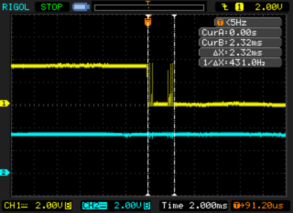
The measurements show that they are within the manufacturers specifications but are not at all what the Xmega is expecting.
After digging around in the Xmega data sheet I confirmed that it has a digital filter which can be set up on the event pins.
The problem with this filter is that it can only be set to a maximum of 8 samples. Each sample is one clock cycle.
This means that on the 32Mhz clock which I am using the greatest width signal it can filter out is 250ns This is far too short for the noise we see here.
So the question is why do Atmel make a chip that cannot decode real world devices? The answer is simple. This encoder is a relatively cheap mechanical encoder.
It costs about $1.00 If you are prepared to spend about $32.00 you can get an optical encoder such as the Bourns ENA1J-B28-L00025L or if you are really feeling flush and want an encoder that does 600 pulses per revolution there is the Omron E6D-CWZ2C 6000P/R which is about $4830.00
These do not have the problems that a cheap mechanical encoder does and are most likely what Atmel had in mind with the Xmega.
Of course you can always use external components to sort out the noise problems but that kind of defeats the object of this exercise.
Not all good
Earlier I spoke about the downside of the Xmega’s event system. Because there is no code running, there is no way that we can change the way the decoder works. It is done by hardware not software. We simply configure the event and the Xmega does the rest and gives us the count and direction in registers. After trying various hacks to get it sorted out I decided that it was time to write my own routine. At first I looked at what was available on the internet. Many were either very simple bits of code that had clearly never been tested in practice, or only detected a single change count for each 4 part step. I wanted something that would count for each and every step and not be prone to errors.
Role our own
Thinking about the problem, we need to be able to filter out the noise. It is not only the noise. We also have the detent right on a switching point which causes the B output to switch even when not turning the knob. We therefore want to ignore any signals that are not part of the expected sequence. So if we are expecting 02310231 but instead get 00231310231 then we need to ignore the parts that we don’t want 00231310231. Ok so lets start. Because this solution is all being done in code it will work with any AVR and indeed almost all other makes of micro controllers.
The first thing that you need is to set a timer to give you a 1ms interrupt. Because this varies between different devices I will leave this part for you to figure out.
We should now have an interrupt routine that is called every millisecond.
In my system, A is connected to PortB.1 and B is connected to PortB.0 The way pin A and B are connected is not important, but you will have to make sure you take it into account as it ‘reverses’ the direction of the information from the encoder.
In our 1ms Interupt Service Routine (ISR) we need this code:
PB0 = PB0 << 1; //this is part of our filter - every time we enter the ISR we shift the previous reading to the left by 1 PB1 = PB1 << 1; //it makes room for the bit we are about to read PB0 = (PORTB.IN & 1) ?PB0 | 1:PB0;//B input - if the pin of PortB.0 is high then OR the variable with 1 PB1 = (PORTB.IN & 2) ?PB1 | 1:PB1;//A input - if the pin of PortB.1 is high then OR the variable with 1 |
These 4 lines of code read in the data from the encoder and form part of the filter. The filter simply sets a bit each time we enter this routine which is every 1ms. If the input is in a constant state we should have a byte which is full of 1’s or full of 0’s. If the input value changes between reads we will instead get a combination of 1’s and 0’s
So in the next line we just decide how many consecutive 1’s / 0’s we need before we can accept that the input is stable. If the manufacturer states that the chatter / bounce is a maximum of 3ms then we need to wait until we see at least 3 1’s / 0’s in a row. This will represent 3 ms because our sample rate is 1ms.
//AND our input variables with 0x07 (three 1's) and see if we get a value of 7 (all 1's) or 0 (all 0's) if(((PB0 & 0x07) == 0x07 || (PB0 & 0x07) == 0 ) || ((PB1 & 0x07) == 0x07 || (PB1 & 0x07) == 0 )) |
At this point we are happy that our signal has settled and is constant, so we will extract the real state of the inputs to a new variable
PBDat = (PB0 & 1) | (PB1 & 2); //PBDat now represents the real value of the encoder at this time |
We are only interested in two things. Did it change since last time we checked? And if it changed is it a valid number?
How do we know if it is valid? Well if the previous number was say 3 then we could say it is only valid if it is 1 or 2 as they are the numbers that should follow 3 depending which way we turn the encoder.
To check if it is valid we enlist the help of a small array which represents the valid sequence of states of our inputs.
By taking the step value we are on and using it as the index to the array we can store the legal next values for that step
unsigned char QDat[] = {0x06,0x0c,0x03,0x09}; |
Those that are following closely will no doubt be wondering how these values relate to our expected values of 0,2,3,1
The reason they don’t look like those values is because we need to check for both sequences 0,2,3,1,0,2,3,1 and 1,3,2,0,1,3,2,0. Now there are many ways to do this,
one is to use a two-dimensional array or even two arrays, but on the day that I wrote the code I chose this one so here goes.
The count between 0 and 3 only requires 2 bits of the byte. So we can store the sequence for one direction in bits 0 & 1 and for the other direction in bits 2 & 3.
Lets assume that the encoder is at the 0 position. If we look at our sequence we can see that when turn it in one direction we will get 2 being the next number or we will get 1 if we turn it the opposite way.
so if we store the 2 in the lower two bits it = 0000 0010 (0x02) and the 1 in the upper two bits 0000 0100 (0x04) combined they become 0000 0110 (0x06)
which you will notice is our first entry in the array. If the encoder is at position 1 then the next legal value is either 3 or 0 so at index one of our array
we store 0000 0000 (0x00) for the 0 and 0000 1100 (0x0c) for the 3 which becomes 0000 1100 (0x0c)
By doing this for each possible value we can ‘look up’ the next legal value in the sequence.
if((QDat[PBDatOld] & 0x03) == PBDat) |
Notice that we are using the previous value of the encoder which is stored in PBDatOld as the index into our array. We AND the result with 0x03 so that only the lower 2 bits are looked at
because we are first checking one direction. If our new value held in PBDat is equal to a legal next value then this statement will be true and we can go ahead with the more mundane duty of
altering the count and deciding on the direction.
PBDatOld = PBDat; if(StepCount == 0) { StepCount = 4; QDir = 0; //set direction if(QuadCount == 0) { QuadCount = MAXCOUNT; } QuadCount--; } StepCount--; |
We do exactly the same for the other direction but this time we use the upper 2 bits in the array and increment the count
else if(((QDat[PBDatOld] >> 2) & 0x03) == PBDat) { PBDatOld = PBDat; StepCount++; if(StepCount > 3) { StepCount = 0; QDir = 1; //set direction QuadCount++; if(QuadCount >= MAXCOUNT) { QuadCount = 0; } } } |
Ok so lets put it all together.
This is the module that contains your 1 ms interrupt code:
#define MAXCOUNT 24 // this must be changed to the number of steps your encoder does in a revolution volatile unsigned char PB0; volatile unsigned char PB1; volatile unsigned char PBDatOld; volatile unsigned char StepCount; volatile unsigned char QuadCount; volatile unsigned char QDir; ISR(<span style="color: #ff0000;">your vector goes here</span>)//occurs every 1ms { unsigned char PBDat; PB0 = PB0 << 1; PB1 = PB1 << 1; PB0 = (PORTB.IN & 1) ?PB0 | 1:PB0;//B PB1 = (PORTB.IN & 2) ?PB1 | 1:PB1;//A if(((PB0 & 0x07) == 0x07 || (PB0 & 0x07) == 0 ) || ((PB1 & 0x07) == 0x07 || (PB1 & 0x07) == 0 )) { PBDat = (PB0 & 1) | (PB1 & 2); if((QDat[PBDatOld] & 0x03) == PBDat) { PBDatOld = PBDat; if(StepCount == 0) { StepCount = 4; QDir = 0; if(QuadCount == 0) { QuadCount = 24; } QuadCount--; } StepCount--; } else if(((QDat[PBDatOld] >> 2) & 0x03) == PBDat) { PBDatOld = PBDat; StepCount++; if(StepCount > 3) { StepCount = 0; QDir = 1; QuadCount++; if(QuadCount > 23) { QuadCount = 0; } } } } } |
Some helpers
This code must not be within your interrupt routine.
Firstly we create two functions which will return count and direction if a change occurs
//-------------------------------------------------------------------- //returns a 1 if the encoder value has changed. //Direction will be changed via pointer given //use GetQuadCount will return the value of the count unsigned char CheckQuad(unsigned char * Direction) { if(ReverseScroll) { *Direction = 1 - QDir; } else { *Direction = QDir; } if(QuadCount != OldQuad) { OldQuad = QuadCount; return 1; } return 0; } //-------------------------------------------------------------------- //return encoder position (0 - 23) unsigned char GetQuadCount(void) { return QuadCount; } //-------------------------------------------------------------------- |
For some applications we don’t actually need the count from the encoder. We only need to know that it changed value and which direction it went
Use it like this
unsigned char Direction if (CheckQuad(&Direction)) //only true if it changed { ScrollMenu(Direction); //scroll our menu up or down } |
If a count is required then this will be how it is called
unsigned char Direction unsigned char Count if (CheckQuad(&Direction)) //only true if it changed { Count = GetQuadCount(); doStuff(Count,Direction); } |
Conclusion
Even though the Xmega built-in Quadrature decoding feature can make reading the decoders simply a configuration, it is not suitable for all decoder types. As can be seen above, writing our own code to do this is a fairly simple task and it is also flexible in that it can be altered to suit our exact requirements.